Injection Mold Design: A Complete Guide for Automotive & Medical Parts

Published on May 25, 2026 · 8 min read

Injection mold design is the single most important factor in determining the quality, cost, and timeline of any plastic part production program. Whether you are manufacturing automotive interior trim or medical device housings, getting the mold design right from the start saves weeks of iteration and thousands of dollars in rework.

In this guide, we break down the core principles of injection mold design as they apply to high-precision industries — from mold structure types and gate design to cooling strategy and material selection.

1. Understanding Mold Types

The mold structure you choose directly impacts part quality, tooling cost, and cycle time. Here are the three most common configurations:

Two-Plate Molds

The simplest and most widely used mold type. The mold splits into two halves — the cavity side (A-side) and the core side (B-side). The part is ejected when the mold opens along a single parting line. Two-plate molds are ideal for simple geometries and are the most cost-effective option. They are commonly used for automotive clips, fasteners, and basic medical housings where the part geometry allows straightforward ejection.

Three-Plate Molds

Three-plate molds add a second parting line that separates the runner system from the molded part. This allows the gate to be placed at the optimal location on the part surface — typically the center or a non-cosmetic area — without manual runner removal. The result is automatic degating during mold opening, which is essential for high-volume production. Automotive grilles and consumer appliance housings frequently use three-plate molds for cleaner gate placement and automated processing.

Hot Runner Molds

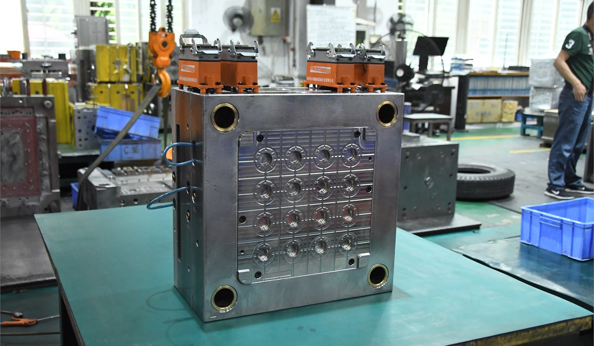
Hot runner systems use heated channels to keep the plastic in a molten state inside the mold, eliminating the runner entirely. This reduces material waste, shortens cycle times, and provides more consistent fill patterns — especially critical for multi-cavity tools. While hot runner molds have a higher upfront cost, they deliver significant savings in high-volume automotive and medical programs where material cost and cycle efficiency are paramount. Systems range from simple single-drop nozzles to valve-gated multi-tip configurations.

Mold TypeBest ForCostMaterial Waste
Two-PlateSimple geometries, low-mid volumeLowModerate
Three-PlateComplex gating, mid-high volumeMediumModerate
Hot RunnerHigh volume, multi-cavityHighMinimal

2. Gate Design

The gate is the entry point where molten plastic flows from the runner into the cavity. Gate design controls fill pattern, weld line placement, and the cosmetic quality of the finished part. Common gate types include:

  • Edge gate: Placed along the parting line. Simple and reliable, but leaves a visible mark. Suitable for non-cosmetic automotive brackets and structural parts.
  • Submarine (tunnel) gate: Angled below the parting line for automatic degating. Leaves a small, often inconspicuous mark — good for visible surfaces.
  • Pinpoint gate: Very small orifice for minimal gate vestige. Used in three-plate molds for parts that demand a clean surface finish, such as medical device housings.
  • Valve gate: Mechanically opens and closes for precise control. Essential in hot runner systems for large automotive panels and parts requiring sequential filling.
  • Direct (sprue) gate: Plastic flows directly into a single cavity. Simple but leaves a large gate mark. Best for thick-walled parts where appearance is less critical.

Gate location should be chosen to minimize weld lines, avoid air traps, and ensure uniform flow. Mold flow analysis (using software like Moldflow or Moldex3D) is indispensable for optimizing gate placement before steel is ever cut.

3. Cooling System Design

Cooling accounts for 60–70% of the injection molding cycle time. An efficient cooling system is what separates a profitable production run from an uncompetitive one. Key principles:

  • Uniform cooling channel spacing: Channels should be evenly distributed relative to the cavity surface, typically 2–3 times the channel diameter away from the part surface.
  • Baffles and bubblers: Used in deep cores where straight drilling is impossible. These redirect coolant flow into hard-to-reach areas.
  • Conformal cooling: Cooling channels that follow the contour of the part surface, made possible by 3D-printed mold inserts. Conformal cooling can reduce cycle time by 20–40% compared to conventional drilled channels, especially for complex automotive and medical geometries.
  • Coolant flow rate: Turbulent flow (Reynolds number > 5,000) is far more effective at heat removal than laminar flow. Design your system with adequate pump capacity and channel diameters.

Poor cooling leads to uneven shrinkage, warpage, and extended cycle times — all of which erode profitability and part quality.

4. Draft Angles and Part Ejection

Draft is the taper applied to vertical walls of a molded part to allow clean ejection from the mold. Without adequate draft, parts can drag, scratch, or even fracture during ejection.

  • Standard draft: 1–2° per side is typical for most applications.
  • Textured surfaces: Increase draft to 3–5° per side to prevent texture drag marks.
  • Deep cores: Up to 1° per 25mm of draw depth as a minimum, with polished surfaces reducing the required angle.
  • Medical and optical parts: Even small draft angles can affect dimensional tolerances, so precise draft planning during the design phase is critical.

Ejection systems (pins, sleeves, stripper plates, or air blast) must be designed to distribute force evenly and avoid part deformation. For delicate medical components, valve ejectors or stripper rings are often preferred over standard pins to minimize stress concentration.

5. Material Selection

The choice of plastic resin affects nearly every aspect of mold design — from shrinkage allowance and gate size to cooling requirements and surface finish. Here are key considerations by industry:

Automotive

  • PP (Polypropylene): Bumper covers, interior trim. Low cost, excellent chemical resistance.
  • ABS: Dashboard components, grilles. Good impact strength and surface finish.
  • PA (Nylon): Intake manifolds, structural brackets. High heat resistance and mechanical strength. Often glass-filled.
  • PC/ABS blend: Interior panels requiring both toughness and surface quality.

Medical

  • PC (Polycarbonate): Device housings, transparent components. Excellent clarity and impact resistance.
  • PP: Disposable medical products, syringes. Sterilizable and cost-effective.
  • PEEK: Surgical instruments, implantable components. Extreme chemical and thermal resistance, biocompatible.
  • POM (Acetal): Precision gears, latching mechanisms. Excellent dimensional stability.

Each material has a specific shrinkage rate (typically 0.4–2.5%) that must be factored into cavity dimensions. Mold flow simulation helps predict actual shrinkage based on part geometry, gate placement, and processing conditions.

6. Mold Flow Analysis: Design Before Cutting Steel

Modern injection mold design should always begin with mold flow analysis. Using simulation software, engineers can predict:

  • Fill pattern and flow front progression
  • Weld line and air trap locations
  • Packing pressure distribution
  • Shrinkage and warpage behavior
  • Cooling efficiency and cycle time estimates

Catching design issues in simulation — before machining begins — can save $10,000–$50,000 in rework costs per tool. For automotive and medical programs where tolerances are tight and volumes are high, mold flow analysis is not optional; it is a prerequisite.

Conclusion

Effective injection mold design requires a systems-level understanding of how mold structure, gating, cooling, draft, and material interact to produce a quality part at scale. Whether you are designing a multi-cavity hot runner tool for automotive production or a cleanroom-certified mold for medical devices, investing in thorough design and simulation upfront pays for itself many times over in production.

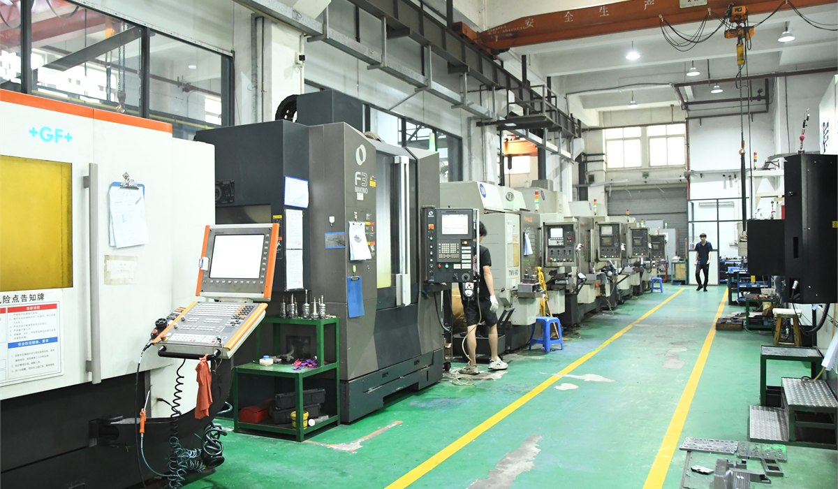
At Huanze Technology, every mold project begins with detailed mold flow analysis and is managed by a dedicated project manager who provides real-time schedule updates from design through T1 sampling. Our 0.003mm measuring accuracy and state-of-the-art 5-axis CNC equipment ensure that your mold is built right the first time.

Ready to Start Your Project?

Contact us for a free quote and mold flow analysis consultation.

Request a Free Quote